Using the Breadboard
A breadboard is a very useful tool to assemble circuits for testing, measurement, and experimental purposes.
Elecronic devices are generally calld components:
- resistors,
- diodes,
- LEDs (Light Emitting diodes)
- Transistors and etc.)
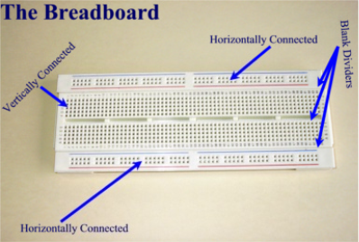
The top and bottom strips (horizontally connected pins) are usually used for power and ground. The central (vertically connected pins) are used for components.
The following examples show how to connect components on a breadboard.
Example 1. Two LEDs in series:
The circuit diagram looks like this:
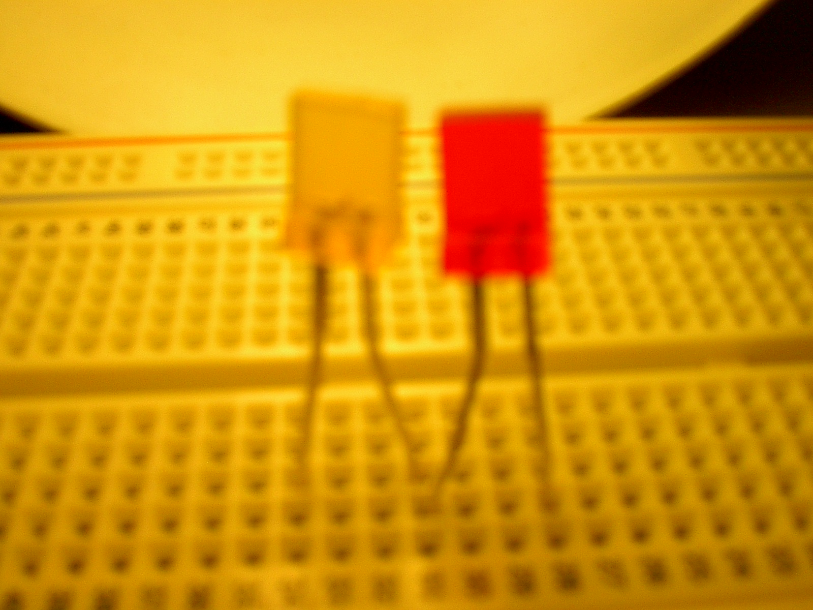
The connection on the breadboard will look like this:
Notice the connection of the yellow LED to the red LED along the same vertically connected pins
Example 2. Two LEDs in parallel: The circuit looks like this:
![]()
The two LEDS actually mounted on the breadboard look like this
- note the two cathodes and the two anodes from the red LED and the Green LED connected respectively along vertical pins.
.gif)